I’ve two Light Dependent Resistor (LDR) boards both using the same base device. A light dependant resistor reduces in resistance the more light that is present. The device I have changes from around 1MOhm in the dark to almost 0Ohms in full light. You should note that many LDRs contain Cadmium Sulphide, a substance currently restricted under RoSH compliance.

The first board I have uses the device in a very simple way. The LDR is in series with a fixed resistor of 10k. So if the ‘-‘ terminal is connected to ground and the middle terminal connected Vcc then the ‘S’ terminal is the centre of a potential divider measuring the voltage across the LDR with respect to ground. In the dark the LDR will have high resistance and drop almost all the voltage, when in bright light the resistance will fall and the LDR will drop very little voltage. The output on the ‘S’ pin will therefore be very close to Vcc in the dark and almost 0 in full sunlight. If connected to an analogue input on the Arduino you can read a representation of the light level like so:
// Simple LDR Test
void setup()
{
  // Start the serial line
  Serial.begin(57600);

  // Setup analog input reference (5v)
  analogReference(DEFAULT);
}

void loop()
{
  int lightLevel;
  float lightLevelVolts, convert;

  // Setup conversion factor
  // 5v reference and 1024 resolution
  convert = 5.0 / 1024;

  while (1)
  {
  // Read the light level
  lightLevel = analogRead(0);

  // Convert to volts
  lightLevelVolts = lightLevel * convert;

  // Print out a message
  Serial.print("Reading: ");
  Serial.println(lightLevelVolts);

  // Wait a short while
  delay(1000);
  }
}
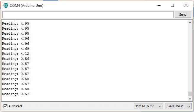
Placing the LDR close to the power LED on the Arduino board is sufficient to drop the voltage to 0.56v, with the LDR pressed against some black foam you can get 4.96v. Simple.
The second board I have from SainSmart is a bit more complex. Is uses the same device with the same series resistor but it also has a 10k resistor across the LDR. The parallel resistor effectively limits the LDR range. When the LDR is at high resistance (1M) the combined value with 10k parallel resistor is effectively 10k (actually very slightly under). When the LDR has low resistance the 10k in parallel has little effect. The overall result is a different response than the standard LDR on its own and is shown on the graph below (LDR resistance along the bottom, combined resistance on the left).

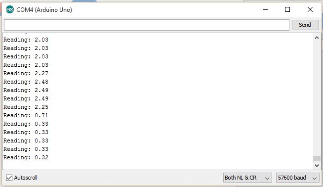
Up to 10k the LDR responds more or less as expected, above 10k the response deadens and flattens out, this makes the device most sensitive to high light level. The other effect is that the LDR effective resistance is limited to 10kOhms. In series with a second 10k, the potential divider centre point will only ever reach 2.5v rather than 5v with the previous board. So it only has half the output range of the previous one. You could remove the 10k parallel resistor and operate the device exactly as per the previous board. So if we run the same code with this device we would expect similar results but half the voltage to be produced.
And sure enough.
Now the second board also has a digital output fed from a comparator. The full circuit is like this.

The LM393 is a comparator with pin 2 the ‘-ive’ input and pin 3 the ‘+ive’ one. When the ‘-ive’ input of a comparator is below the level of the ‘+ive’ input the output is low and vice versa. The ‘+ive’ input is fed from a variable resistor across the supply and so can be set anywhere between 0v and Vcc. The LDR voltage is fed to the ‘+ive’ input and we already know falls when it get light so when enough light is available the ‘+ive’ input will fall below the ‘-ive’ one and the digital output goes low. There is also an indicator LED on the digital line (and a separate pull up resistor) for reference and board power light (note the LED comes on when the output goes low).
This can be easily tested with some slightly modified code. Measuring the variable resistor with a meter the set point is currently 1.39v so we should see the digital line switch at this level. So here goes:
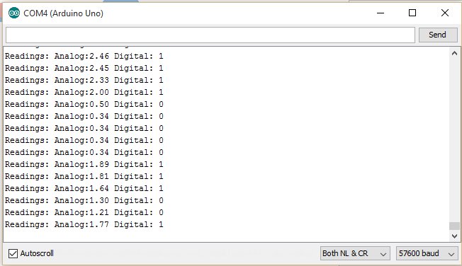
So we can still see a maximum voltage of 2.46v and a minimum of 0.34v, approximately what is was before, with the digital output high and low appropriately. The last four values show the digital line switching between somewhere 1.30v and 1.64v which is around what is expected.
The comparator board from SainSmart is a generic board used for a couple of other sensors plus half a dozen Xinda using what look to be basically the same circuit in slightly different form factor. Personally I’d would have maximised the voltage range rather than limiting it to half Vcc given that the variable resistors range goes to full Vcc , seem that half the range is wasted. I’m also not entirely convinced about the parallel 10k resistor across the LDR but that’s just a scaling feature. The 10k pullup on the digital output is also not needed if the LED (and it’s limiting resistor) are fitted. The LM393 comparator is good from 2.0v to 36.0v so can be used over a wide supply range with the digital and analogue outputs maintaining a full (well very close to) 0v to Vcc swing.
